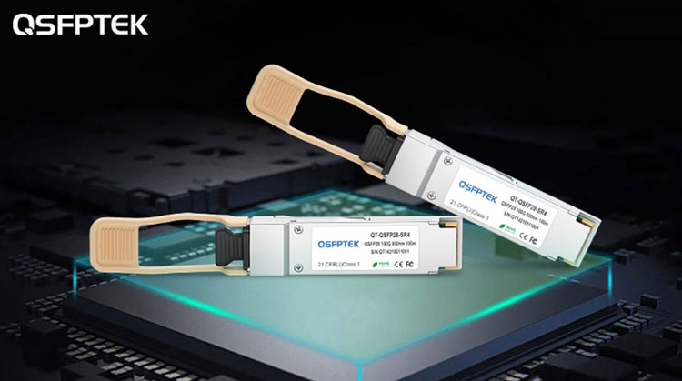
With the rapid development of data communication and telecommunication technology, the capacity of the optical network has surged. As the core device of high-speed broadband optical communication systems and networks, the high-speed optical module has become a hot research topic in the field of optical communication. Higher speed, miniaturization, low power consumption, and intelligence, is the development trend of optical modules. This article will introduce the basic performance parameters of optical modules to help you have a deeper understanding of optical modules.

Basic performance parameters of optical transceiver module
When the optical module is working, in order to accurately describe its working performance and status, a series of performance parameters are defined. The basic performance parameters of the optical transceiver module mainly include:
(1) Center wavelength: the optical band used for optical signal transmission. At present, there are mainly three central wavelengths of optical modules: 850nm band(10G SR SFP+, 40G SR4 QSFP+, 100G SR4 QSFP28), 1310nm band(10G LR SFP+, 40G LR4 QSFP+, 100G LR4 QSFP28) and 1550nm band(10G ZR SFP+).
(2) Transmission rate: the average amount of information passing through the channel in unit time. Generally, there are two representation methods of bit rate and symbol rate. For binary symbols, the bit rate and symbol rate are equal, and the unit is bit/s.
(3) Transmission distance: the maximum distance that the module can transmit error-free in a specific optical fiber transmission system. The transmission distance of optical modules is divided into three types: short distance, medium distance and long distance. Generally, 2km and below are considered to be short distance, 10~20km is medium distance, and more than 30km is long distance. The factors that affect the transmission distance are fiber (loss, dispersion, etc.), laser (power, wavelength, working mode), detector sensitivity, transmission rate, etc.
(4) Average optical power: the average value of the instantaneous transmitted optical power in the period. When a pseudo-random signal is sent, the “1” and “0” in the data signal are roughly half each, and the power measured at this time is the average transmit optical power.
(5) Extinction ratio: the average optical power is A when the optical data are all “1”, and the average optical power is B when the optical data are all “0”, then the extinction ratio is EX A B =10lg / ( ) . If the extinction ratio is too large, chirp will be caused, the spectrum will become wider, and the dispersion will become larger; if the extinction ratio is too small, it will be difficult for the receiver to separate the “1” and “0” in the optical signal.
(6) Eye diagram: The eye diagram includes the characteristics of signal rise time, fall time, pulse overshoot, pulse undershoot and oscillation.
(7) Receiving sensitivity: The minimum optical power that the module can receive under the condition of a certain bit error rate.
(8) Receiver overload power: the highest average optical power that the receiver can receive when the specified bit error rate is reached.
(9) Jitter: The short-term deviation of each effective instant of digital signal relative to the theoretically specified time position. The unit of jitter is UI, which is the reciprocal of the optical transmission bit rate.
When using an optical module, an appropriate optical transceiver module can be selected according to the needs through the description of the performance parameters, and at the same time, the measurement of the relevant parameters can determine whether the optical module fails.
related store
TBD

Leave a Reply